Technical Article
How to Calculate Wire Size & NEC 690.8 (B)
Proper wire sizing is fundamental when designing and installing a PV system. The National Electrical Code (NEC) stipulates guidelines on wire sizing that, if complied with, can help keep your projects operating more safely and efficiently. The entire journey for proper wire sizing and coordination with even a basic NEC-compliant solar PV design is a lengthy and involved journey. The steps could go something like this:
- Locate the short-circuit current (Isc) based on the module specifications.
- Apply a 125% overcurrent factor per 690.8(A) to account for high irradiance conditions that boost the modules’ ability to produce current. This is defined as the maximum current of the PV circuit.
- Apply 690.8(B) to choose a wire size with adequate ampacity, modifying for ambient temperature and conduit fill, where applicable.
- Check voltage drop, aiming for less than 2-3% loss of efficiency.
- Size overcurrent protection devices- most often, 125% of our maximum current value as defined in 690.8(A).
This article will focus mainly on the third step in this process and walk through an example of calculating wire size for a PV system, as spelled out by a few key sections within Article 690.8 Circuit Sizing and Current and relevant tables elsewhere in the 2023 NEC.
Why size appropriately?
If you find yourself here, chances are good that you already have some basic understanding of how current in or on a wire behaves and why it’s crucial to specify and install properly rated conductors. Choosing a wire size rated wildly above a given maximum circuit current (with the proper adjustments described below), while compliant with code, is not within best practices for design and budgetary reasons. For larger projects with many conductors, especially, pulling a smaller gauge of wire costs less than a thicker one, all other things equal.
Rate, design, and specify too far below the adjusted max circuit current and you take on some noticeable performance and safety risks. Recalling that thinner wire overheats more readily than a thicker gauge of wire, these risks include damage from heat, potential fire, reduced power output, and efficiency of the PV System related to excessive voltage drop. The code charges us to follow proper sizing procedures to avoid these safety hazards.
How do I calculate PV conductor sizes per 690.8(B)?
Traditionally, the industry has reduced our compliance options for NEC 690.8 (B) to two basic paths. They are given to us in the charging statement of 690.8(B) explicitly:
NEC 2023: 690.8 (B) Conductor Ampacity. Circuit conductors shall have an ampacity not less than the larger of 690.8(B)(1) or (B)(2).
(1) Without Adjustment and Correction Factors. The minimum conductor size with an ampacity not less than the maximum currents calculated in 690.8(A) multiplied by 125 percent.
(2) With Adjustment and Correction Factors. The maximum currents calculated in 690.8(A) with adjustment and correction factors.
Importantly, notice that the wires we are sizing “shall have an ampacity not less than the larger of” the two. So, we must calculate both ways and use the higher ampacity value.
Take the case of a grid-tied PV System as a working example. Each section of the PV system has circuit conductors that must be sized.
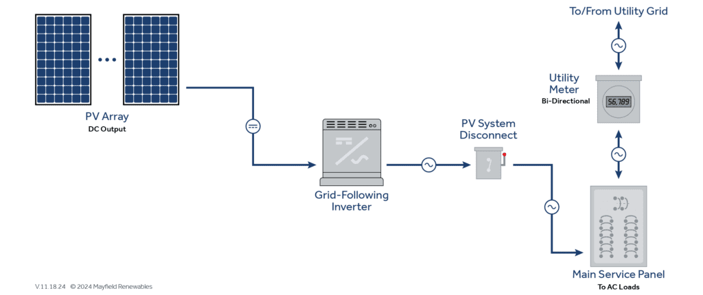
For the sake of a concise example, consider the circuits on either side of the interactive PV inverter. The 2023 NEC streamlines these terms: the “PV source circuit” and the “Inverter output circuit.” in Article 100. Take a look at these definitions; free trials of NFPALiNK here.
Our example here will demonstrate sizing for a PV Source Circuit wire.

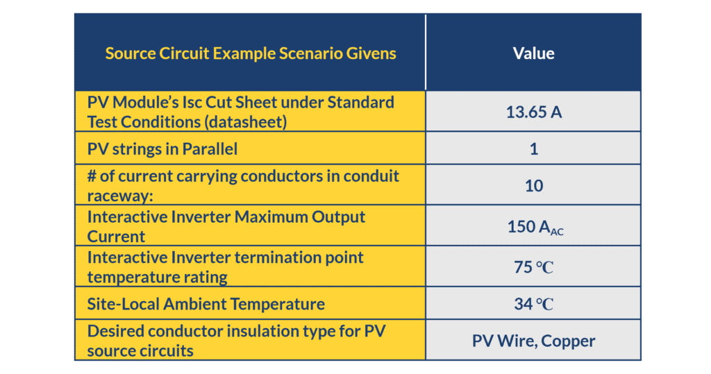
How to Size This PV Source Circuit
Step 1: Locate the maximum circuit current based on the module specifications. Per the data-sheet:
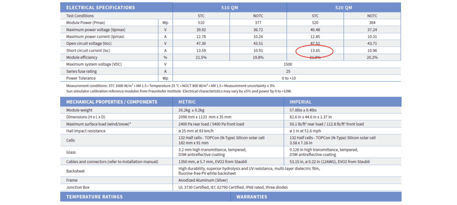
Step 2: Calculate Maximum Current: The PV module with a short circuit current, Isc, under standard test conditions. Per 690.8 (A)1(a) for this example.
Maximum Current: Isc x 1.25 x # in parallel
13.65 A x 1.25x 1 = 17.06 A
Maximum Current: 17.06 A
Step 3: Apply 690.8(B) to choose a wire size with adequate ampacity, modifying for ambient temperature and conduit fill, where applicable.
We need the larger wire size ampacity rating of 690.8(B)(1) without adjustment factors or (B)(2) with adjustment factors.
(B) (1) Without Adjustment and Correction Factors
If you hear folks referring to the “156% factor for PV circuits,” they are referring to this. 125% twice is 156%.
(B)(1) Minimum conductor ampacity rating: Maximum Current from 690.8(A) x 1.25
17.06 A x 1.25 = 21.30 A
(B)(1) Minimum conductor ampacity rating: 21.30 A
Given this information, we can head to Article 310 to find our wire gauge. To properly apply this Code section, we need to consider the size and temperature rating needs of the wire in (B)(1) at its termination point, the inverter. The ampacity of the entire circuit is constrained by the temperature value at the exposed wire. In the case of our example, the termination point is rated at 75°C.
The goal is to find the smallest wire that exceeds the minimum conductor ampacity of 21.30 A in the temperature rating column we need per our inverter termination point. Our given inverter terminal temperature rating for this example is 75℃, so we can select the AWG 12 which is rated 25 A.
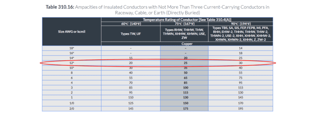
(B)(1) wire size recommended: 12 AWG Copper PV Wire
(B) (2) With Adjustment and Correction Factors
This subsection looks at the insulated conductor beyond the terminations we looked at above. The adjustments we need to make to our rating are based on two conditions of use: temperature and number of current-carrying conductors in a raceway, also known as “conduit fill”. These two conditions of use will refer us to a couple of tables in 310 tables. For this example, these are:
Table 310.15(B)(1) – for temperature
Table 310.15(C)(1) –for conduit fill
The ambient temperature in this example was given to us: 34℃. Looking then at 310.15(B)(1):
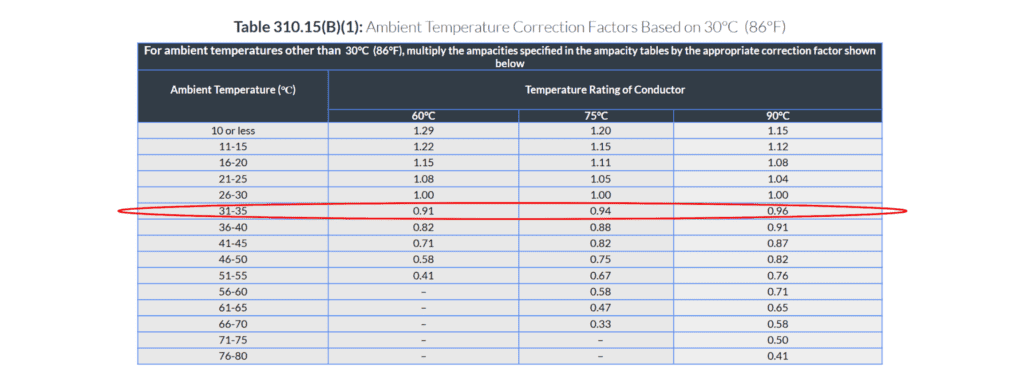
Our desired insulation class is the PV Wire. They have an outer jacket rating of 90℃. So our factor here then is 0.96. This is to say, given the temperature to which the current carrying conductors are exposed, we lose 4% of the current carrying capacity.
For conduit fill, we look to Table 310.15(C)(1) for this example.

We have 10 conductors in the conduit, so we will also apply the factor of 0.50. This represents a loss of half the current carrying capacity with this conduit fill.
At this point, we can apply these factors to the 310.16 Ampacity ratings for the wire we selected in B(1) to make our comparison.
We had landed on 12 AWG Copper wire. In the 90℃ column, 12 AWG is rated for 30 A (see above 310.16 (B)(1) ):
30 A x Temperature loss factor x Conduit full loss factor =
30A x 0.96 x 0.50= 14.25 A
What B(2) here asks us is “Is this factored rating larger than the Maximum current calculated in 6908 (A)?” 690.8(A) calculated as: 17.06 A
14.25 A rating is not larger than 17.06 A rating. We need to try the next largest gauge.
In the 90℃ column, 10 AWG is rated for 40 A (see above 310.16 (B)(1) ):
40 A x Temperature loss factor x Conduit full loss factor =
40A x 0.96 x 0.50= 19.2 A
19.2 A > 17.06 A. So (B)(2) satisfied
(B)(1) recommended wire size: 12 AWG Copper PV Wire
(B)(2) recommended wire size: 10 AWG Copper PV Wire
We need the larger of the two, per 690.8(B). So, 10 AWG Copper PV Wire, it is. From here, we would be ready to move onto subsequent steps: to check for voltage drop and to size overcurrent protection devices.
Further Code Considerations
Many complexities arise with various PV projects beyond the basic example provided, and the NEC offers solutions for addressing them. For example:
- Utilizing 8760-hour modeling data to establish maximum source circuit current by using 690.8(A)(1)(a)(2) for larger kW capacity PV systems
- For designs that include PV Arrays with DC-to-DC converters 690.8 (A)(1)(b)
- Navigating circuit sizing in tandem with OCPD sizing given the rounding rules of 240.4(B)
If you’re left with more questions than answers when considering your project's wire sizing specifics, that’s okay. Delve deeper with Ryan Mayfield into 690.8 (A), 690.8 (B), and 690.9 as they inform calculating wire sizes Ryan tackles these topics in a workshop at your own pace, NEC 2020 and 2023 for PV Systems (Parts 1 – 3). Hint: Check out Lessons 5-7 of Part 1, and happy sizing!
Mayfield Renewables is a technical consultancy specializing in commercial and industrial PV and microgrid engineering. Contact us today for a consultation.


