Technical Article
How to Calculate PV Voltage Drop
The term voltage drop refers to the reduction of voltage between components in a circuit. Voltage drop is used to determine conductor size and length, as well as the spacing between circuit components. Generally speaking, we want to minimize voltage drop losses to maximize total energy harvest from the PV array.
Experienced PV engineers have likely heard of the “2% DC voltage drop” rule of thumb, which we analyzed back in 2020. In this article, we will cover the concepts and calculations behind voltage drop – what it is, why it matters, and how to determine voltage drop losses for DC and AC conductors.
What is voltage drop?
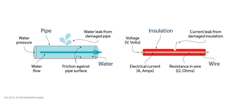
No conductor is perfect. At normal operating temperatures, all conductors will resist the flow of electricity, and a portion of the circuit’s electrical energy will be used to overcome the conductor’s resistance. A conductor’s resistivity or resistance (a material property unique to that type and size of conductor) will determine how much electrical energy is dissipated as heat.
If we know a conductor's resistance rating and the amount of electrical current that will flow through it, we can quantify the voltage drop or the voltage required to move current from one end of the conductor to the other.
Why does voltage drop matter?
The impacts of voltage drop change on the DC and AC sides of the system. We covered the DC considerations in-depth in an earlier article. A few other DC- and AC-side considerations are as follows:
Inverter operation. PV inverter spec sheets will list a DC input voltage range. When the DC input voltage falls outside of the operating range, the inverter will cease production. DC voltage drop from the PV array circuits to the PV inverter should be limited such that the input voltage remains within the operating range for as many hours of the day as possible.
Dollars and cents. System owners want to reduce both DC and AC voltage drop to squeeze as much energy as possible from their PV array. Any drop in production results in fewer kilowatt-hours to power loads or to sell back to the grid. Meeting AC production estimates is especially important for larger systems with power purchase agreements or other financing mechanisms in place.
Utility interconnection. Since the inverter has to push current from the PV system to the grid, the inverter will have to raise its voltage to overcome the losses associated with voltage drop. Therefore, if there is a 2% voltage drop between the inverter and the utility interconnection, the inverter will have to raise its output voltage by 2% to have both a higher voltage than the utility and enough voltage to overcome the losses due to voltage drop. If the utility voltage is already at the upper end of the permissible range (above nominal), then there is a risk that the inverter will have to raise its voltage too high and trip off because of IEEE interconnection standards.
How do I calculate voltage drop?
Voltage drop calculations build off of Ohm’s Law, a fundamental electrical engineering equation that relates voltage (V), current (I), and resistance (R).

We can rearrange the equation to solve for any of the three values so long as we already know two of them. No rearranging is necessary to find the voltage drop, but we need to add a few more values to quantify the resistance of our conductor.
Returning to the water pipe example, resistance is analogous to friction. A conductor’s resistance depends on its material and physical properties. We account for these with a few adjustments to the Ohm’s Law equation. Let’s first look at the equation to calculate DC voltage drop:

The variables to find DC voltage drop are as follows:
- VD% = Percent voltage drop (the calculated voltage drop divided by the source voltage multiplied by 100)
- 2 X L = 2 times the one-way circuit length (e.g., two times the distance from a module string to the input terminal in the inverter)
- I = Module maximum-power current (Imp) at standard test conditions (STC, or 25°C)
- R = Conductor resistance at 75°C (as found in Chapter 9, Table 8 in the 2023 NEC)
- 1,000 = Dividing by 1,000 to account for kilo-level units (e.g., from kW to W)
- Vsource = Souce maximum-power voltage (Vmp, conservatively adjusted to the ASHRAE 2% design temperature)
To find AC voltage drop in a three-phase circuit, we swap in a factor of √3 to account for sinusoidal AC voltage. The new equation will look like:

Of course, as with any engineering problem, it’s not always as simple as plugging a short list of inputs into a single equation. The methods described above can be used for simpler systems and back-of-the-napkin calculations. In reality, many utilities, AHJs, developers, and system owners will have their own requirements for DC and AC voltage drop limits and calculation methods. Circuits that include a transformer (and thus, push current through long coils inside the transformer) will have a significantly higher voltage drop and must be accounted for using manufacturer data and voltage taps. Best practice is to understand the local engineering requirements for your project and its components and to adjust your voltage drop calculation methods accordingly.
Mayfield Renewables is a technical consultancy specializing in commercial and industrial PV and microgrid engineering. Contact us today for a consultation.

