PV Disconnect Placement per NEC 2017 Article 690.1
Engineers, designers, installers, and manufacturers need to stay on top of jurisdictional code changes to ensure their products and systems will operate safely. Local regulations will vary, but there is perhaps no code more important to photovoltaic (PV) manufacturers, designers, and installers than the National Electrical Code (NEC) Article 690, which provides electrical requirements for solar PV systems. In this post, we will outline the 2017 Code updates as they pertain to PV system disconnects.
Prior to applying specific Code rules around PV system disconnects, it’s imperative to know how the Code defines a PV system. This is an important point that can be applied to nearly all situations when reading Code: When in doubt, take a look at the definitions. Per NEC Article 100, a “PV system” is defined as “The total components and subsystem that, in combination, convert solar energy into electric energy for connection to a utilization load.” In accordance with this definition, a PV system disconnect must isolate these specific components.
Given the many possible system configurations, however, finding the appropriate location for a PV system disconnect is not always as simple as it may seem. The best way to apply the rule is to consider what is being disconnected according to the single-line diagram. Ask yourself: Am I disconnecting all the equipment required to convert solar energy into electric energy? Will all the downstream equipment (equipment still connected within the system) operate properly without the power source I just disconnected? Let’s run through a few examples to illustrate.
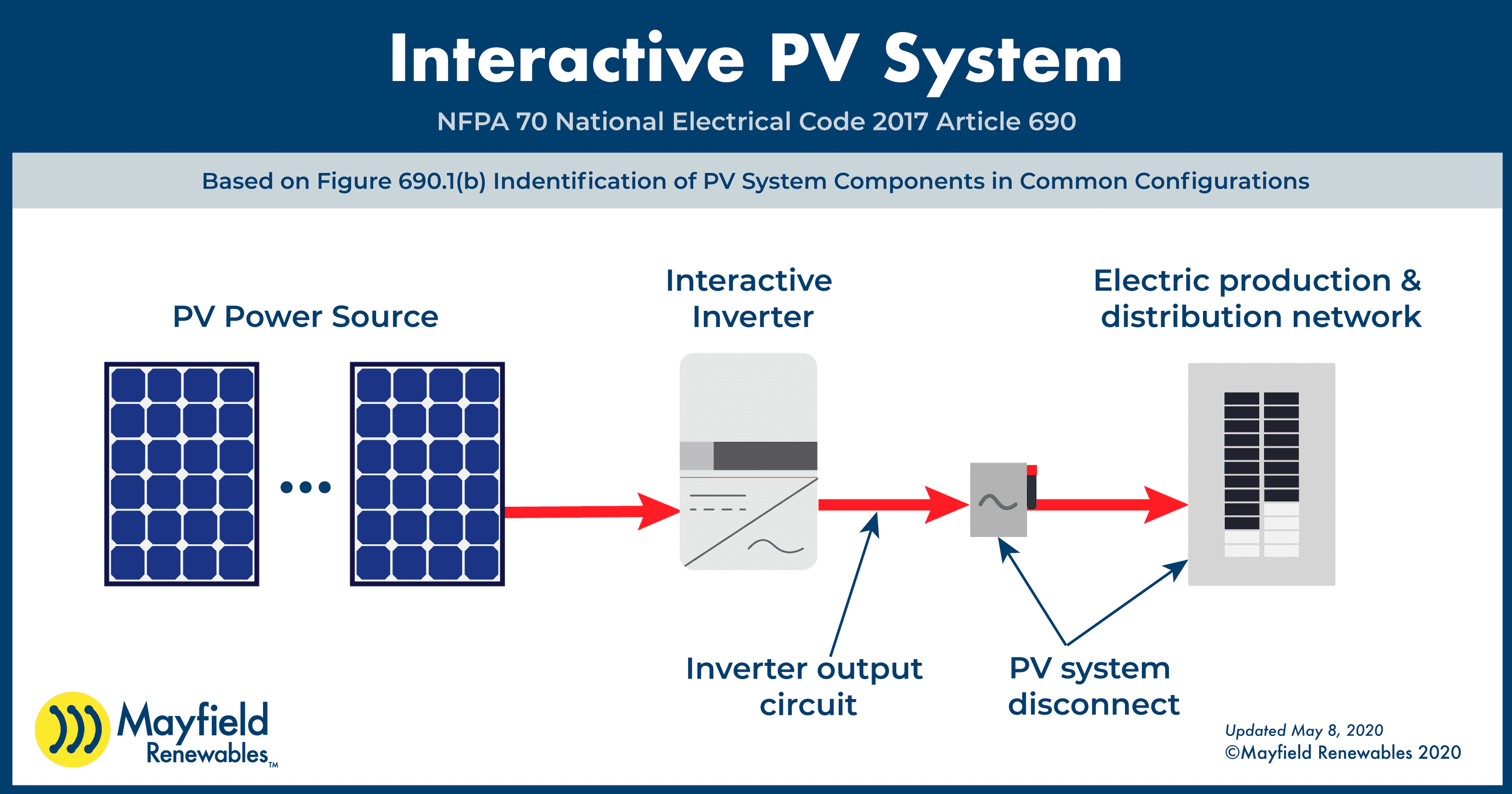
The most straightforward example is to consider a grid-direct PV system that uses a grid-direct inverter as shown in the image below. In this system, the PV power source is connected to a grid-direct, interactive inverter that is then connected to a distribution network (utility-provided) system.

In this example two possible PV system disconnect locations exist. The external disconnect, shown as the switch between the inverter and the electrical panel, may not be a Code or utility requirement for the system per your local authority having jurisdiction (AHJ). If that is the case, the breaker in the electrical panel would be considered the PV system disconnect. In some cases, the external switch may be required to meet either local utility and/or NEC requirements. If installed, this could be considered the PV system disconnect.
The way to evaluate this is to again ask: “Am I disconnecting all the equipment required to convert solar energy to electrical energy?” In both cases, the answer here would be yes. Either the external disconnect or the breaker in the electrical panel disconnects all the equipment that is part of the PV system converting the solar energy to electrical energy.
A common question we hear is “What about the integrated DC disconnect on the inverter? Would that be considered the PV system disconnect?” That disconnect does isolate the PV power source from the rest of the system but it does not isolate all of the PV equipment. The DC disconnect will stop the inverter from producing power but the AC side of the inverter will still be connected to the utility. Therefore this wouldn’t be considered the PV system disconnect as not all the PV equipment is disconnected.

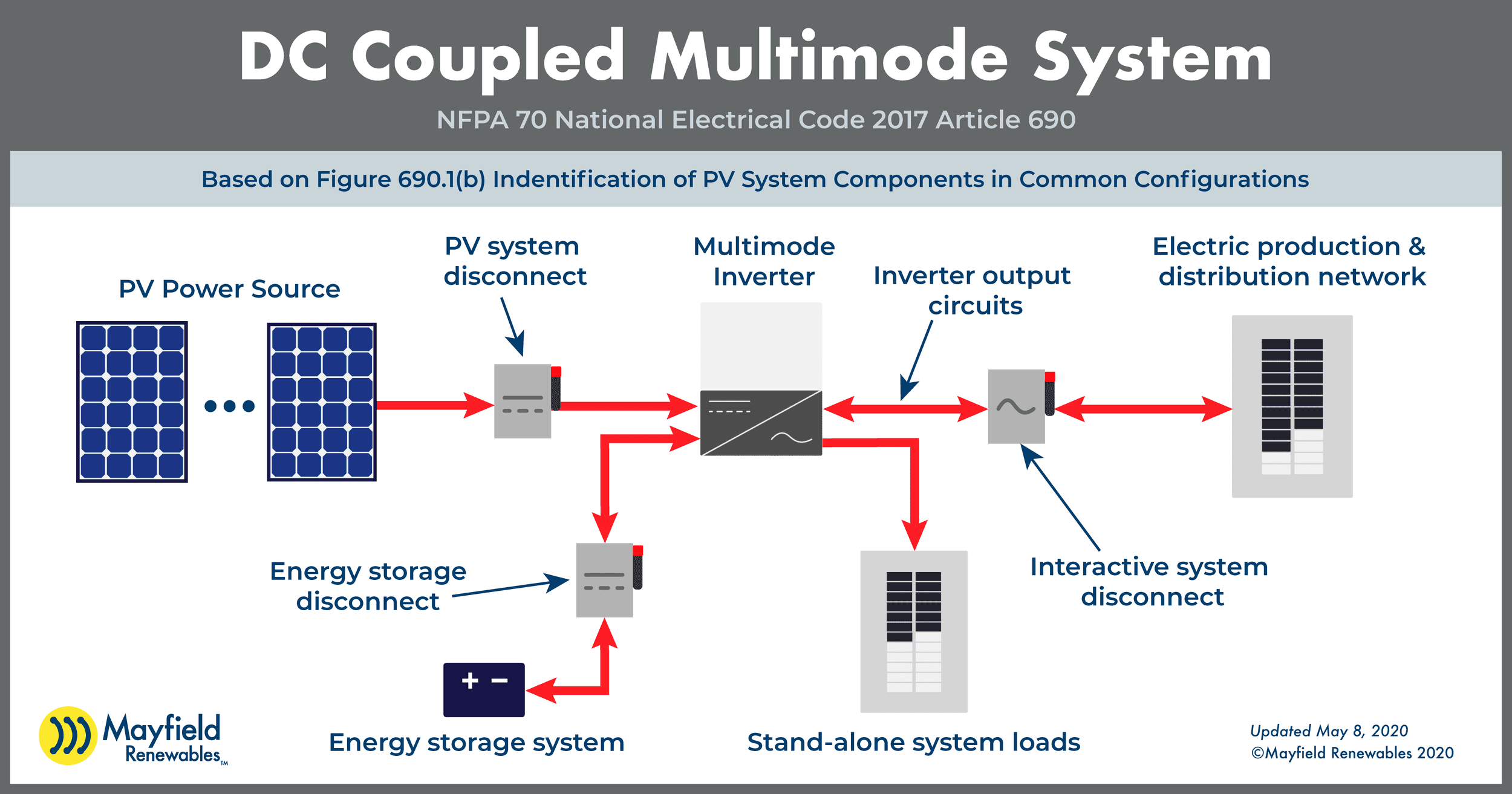
Of course, it wouldn’t be Code if there weren’t special cases and exceptions. Shown above is a typical DC-coupled multimode system with a PV array, energy storage, and essential loads panel. In this example, the PV system disconnect is placed immediately following the PV array, cutting it off from all other components downstream.
Again, let’s ask: Am I disconnecting all the equipment required to convert solar energy into electric energy? And while the multimode inverter and storage system are important to the overall functioning of the system, the PV-specific components are not required for their operation. The multimode inverter will continue to pull power from the energy storage system and distribute that power to the essential loads panel and/or main service panel. The backup system can continue to operate without the PV modules.
This is a scenario where the PV system disconnect is on the DC side of the inverter. Therefore, we can’t make blanket statements about the location of the PV system disconnect for all systems in relation to the inverter.

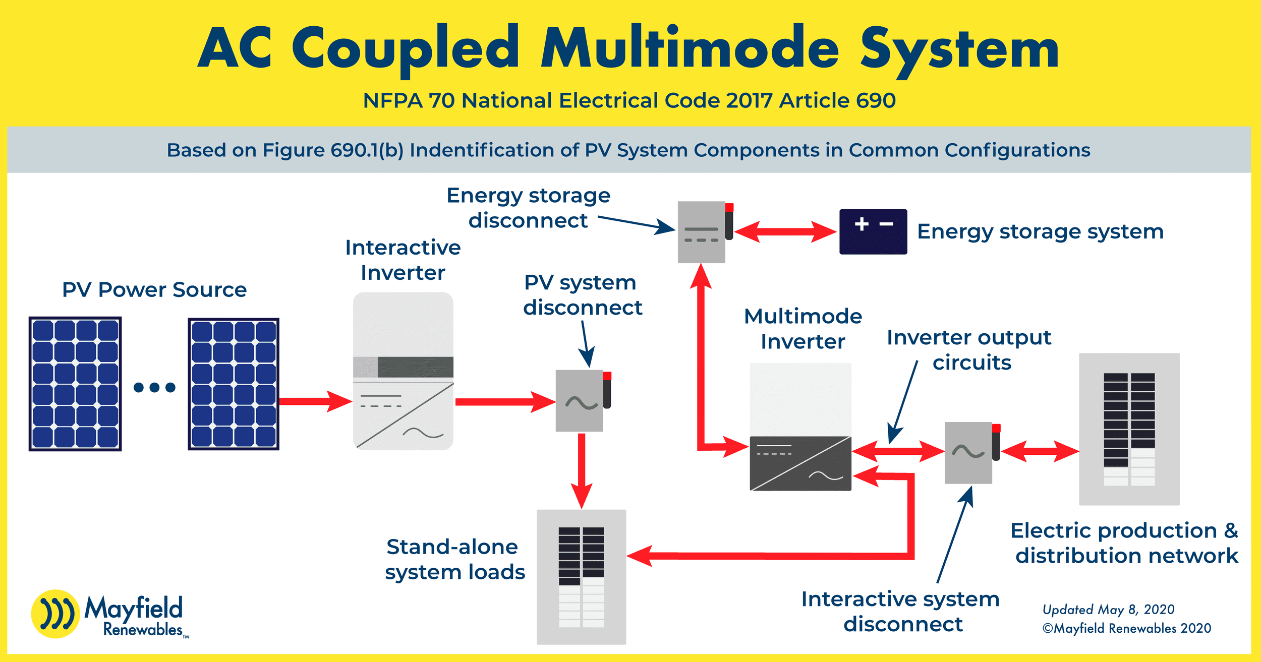
In the final example, let’s look at an AC-coupled multimode system. This system provides power to dedicated loads similar to the DC-coupled system, it just uses different equipment to do so. After the DC output from the PV modules runs through an interactive inverter or microinverter(s), the AC output power feeds a supply panel (shown as the “stand-alone systems loads”), which in turn feeds the multimode inverter connected to the energy storage system and main service panel.
In this system, the PV disconnect is positioned on the AC side of the interactive inverter, similar to the grid-direct example above. Once more, let’s confirm: Am I disconnecting all the equipment required to convert solar energy into electric energy? Again, yes–the multimode inverter will continue to operate and distribute power throughout the system even without power from the PV array.
Differentiating the location of the PV system disconnect is important because of the implications for other requirements such as rapid shutdown. The requirements for rapid shutdown apply to “PV system circuits installed on or in buildings…” So if we can accurately define where the PV system disconnect is in this context, we can then define which conductors require rapid shutdown control.
We understand that system design and NEC application can be a complicated process, and we’re here to help. We offer a suite of design services ranging from full plan sets to PVSyst reports to everything in-between.


